Now in our last topic, we configured a “Layer2 Etherchannel”, and that might be very
appropriate, If we had end to end Vlan’s in the Enterprise, another words, we
got Vlan’s in Building 1, Vlan’s in Building 2 and Vlan’s in Building
3, and all the same. They are being shared between all those buildings,
and we have Trunks interconnecting our buildings
and case like that.
We might want to use “Layer2 Ether-channel’s”,
however if we have a “Local Vlan’s” deployment, we might have Vlan’s within building 1,
and the different set of Vlan’s within building 2, and different set of Vlan’s
within building 3, and to get between buildings. Instead of sending traffic
over a “Layer 2 Trunk”, we “Route between Buildings”. We need to leave a building not
over a Trunk but over a “Routed Port”. We can do that with a Layer3 Etherchannel.
“A Layer 3 Etherchannel
is a connection made up of, a group of bundle ports, which we put into a
logical interface, and those ports on that logical interface, they routed
ports, instead of switchports”
Let’s take a look? How to set it up
Ø SW2(config)#interface
range fastethernet 0/1-2
Ø SW2(config-if-range)#speed
auto
Ø SW2(config-if-range)#duplex
auto
Ø SW2(config-if-range)#mdix
auto
ü Reason
we doing that is we wanna make sure that, we can use MDI-X, which were requires the “Speed and Duplex” to be set to “Auto”. MDI-X is
gonna let me use Straight-Through Cables to
interconnect these switches.
Now let’s convert these “Switchport”
into the “Routed Port”
Ø SW2(config-if-range)#no
switchport
ü Now fastethernet 0/1 and 0/2, they are now Routed Ports, we can could go in, and assign those “individual IP Addresses”. However instead, we want to
bundle them together into the “Logical Etherchannel”.
Let’s use that Channel-group
command again to create Virtual-Interface
Ø SW2(config-if-range)#channel-group
1 mode on
ü 1:- locally significant number
ü ON: - This way, we are not sending PAGP frames, we are not sending LACP frames, we just saying these this port to be a channel.
Let’s go into that Channel now.
Ø SW2(config)#interface
port-channel 1
Ø SW2(config-if)#no
switchport
ü To
make sure that, this Virtual interface is also viewed as a Routed interface,
not a Switch interface
Now assign an IP Address, because this
is a Routed Port.
Ø SW2(config-if)#ip
address 10.1.1.1 255.255.255.252
Once we set up, we want to confirm that
we really are exchanging a Route information via OSPF, to do that, we want to
create a loopback interface.
Ø SW2(config)#interface
loopback 0
Ø SW2(config-if)#ip address 2.2.2.2 255.255.255.255
Ø SW2(config-if)#ip address 2.2.2.2 255.255.255.255
Now setup some Routing, let’s use OSPF. First we have to enable the IP Routing, which is disabled by default.
Ø SW2(config)#ip
routing
Ø SW2(config)#router
ospf 1
ü 1:- Process ID, locally significant
Ø SW2(config-router)#network
0.0.0.0 255.255.255.255 area 0
ü Route
for all networks, shortcut way
Done with Configuration on SW2.Let’s go
over SW3 and give a similar Configuration
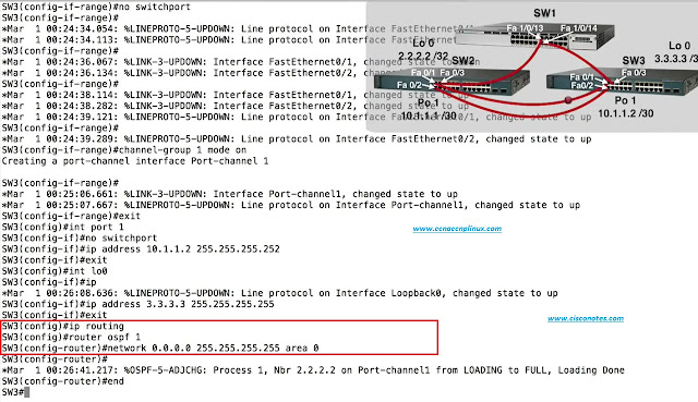
Ø SW3(config)#interface
range fastethernet 0/1-2
Ø SW3(config-if-range)#speed
auto
Ø SW3(config-if-range)#duplex
auto
Ø SW3(config-if-range)#mdix
auto
Ø SW3(config-if-range)#no
switchport
Ø SW3(config-if-range)#channel-group
1 mode on
ü Remember
the other side is ON, it’s not gonna be sending
or responding to PAGP or LACP frames, and as result the channel will be formed.
Ø SW3(config)#interface
port-channel 1
Ø SW3(config-if)#no
switchport
Ø SW3(config-if)#ip
address 10.1.1.2 255.255.255.252
Ø SW3(config)#interface
loopback 0
Ø SW3(config-if)#ip
address 3.3.3.3 255.255.255.255
Routing
Configuration:-
Ø SW3(config)#ip
routing
Ø SW3(config)#router
ospf 1
Ø SW3(config-router)#network
0.0.0.0 255.255.255.255 area 0
ü Everybody
belong to Area 0
These
switches now acting as Layer3 or Multilayer Switches. They are doing routing.
Verification & Troubleshooting: -
Ø SW3#show ip
interface brief
ü Make
sure that, we have a newly created Virtual Interface
Now let’s make sure that, OSPF
Neighborship formed over
the Etherchannel
Ø SW3#show ip
ospf neighbor
Now verify, have we learned any Network Information
via OSFP over that
Routed link
Ø SW#show ip route
Now go to SW2 and use same command
Ø SW2#show ip
route
Conclusion: - That’s the
look, creating a Layer3 Etherchannel for times,
we want to have some extra bandwidth on a Routed Link interconnecting
a couple of Multilayer Switches.
If You Like the Post. Don’t forget
to “Subscribe/Share/Comment”. Thank You.


0 comments:
Post a Comment